Deploy vSphere with Kubernetes (Project Pacific) – Part 5: Configure NSX-T
This Post is part of a series:
Deploy vSphere with Kubernetes (Project Pacific) – Part 1: Inventory and Design
Deploy vSphere with Kubernetes (Project Pacific) – Part 2: Prepare base networking
Deploy vSphere with Kubernetes (Project Pacific) – Part 3: Prepare base storage (FreeNAS)
Deploy vSphere with Kubernetes (Project Pacific) – Part 4: Install NSX-T
–> Deploy vSphere with Kubernetes (Project Pacific) – Part 5: Configure NSX-T
Deploy vSphere with Kubernetes (Project Pacific) – Part 6: Some basic testing
Deploy vSphere with Kubernetes (Project Pacific) – Part 7: Enable Workload Management
Deploy vSphere with Kubernetes (Project Pacific) – Part 8: Deploy first Workloads
In this part, we are going to configure the NSX-T network. More detailed, we will configure the following:
- Compute Manager
- Transport Zones
- Configure Transport nodes
- ESXi Node Uplink Profile
- Create IP Pool for ESXi VTEPs
- ESXi Transport Node Profile
- Prepare the ESXi Transport Nodes
- Configure Edges
- EDGE Node Uplink Profile
- Create IP Pool for EDGE VTEPs
- Deploy the NSX-T Edges
- Add EDGE to EDGE Cluster
- Create and configure Tier-0 Gateway (aka T0 Router)
But before all of this, let’s do a bit theory.
Besides all the new features in NSX-T 3.0 and the improvements in the GUI, it also made a few things easier and more flexible.
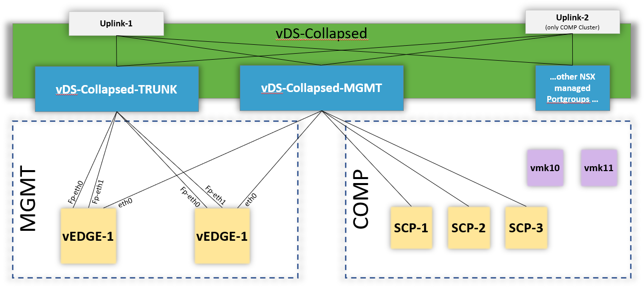
Up until NSX 2.5.1, your ESXi Transport Nodes had to use dedicated n-vDS Switches. Thus, you had to dedicate vmnics to the NSX environment (because you can’t have a vmnic connected to two different vSwitches).
NSX-T 3 can now also utilize an existing VDS, instead of creating its own n-vDS. And in fact, that is the recommended way for vSphere with Kubernetes.
Compute Manager
Let’s start with connecting our NSX-T Manager to our vCenter.
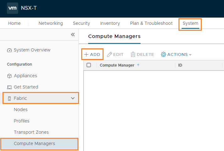
Login to NSX-Manager and navigate to System –> Fabric –> Compute Manager –> + Add
In the “New Compute Manager” screen, configure the following:
- Name: vcsa-1 (just a descriptive name)
- FQDN or IP Address: vcsa-1.cloudborn.lab
- HTTPS Port of Reverse Profy: 443
- Username: administrator@vsphere.local (if you provide another user, make sure it has sufficient permissions – check here)
- Password: ********* (i wonder why this many stars actually don’t work as a password … ^^)
- Enable Trust: Yes
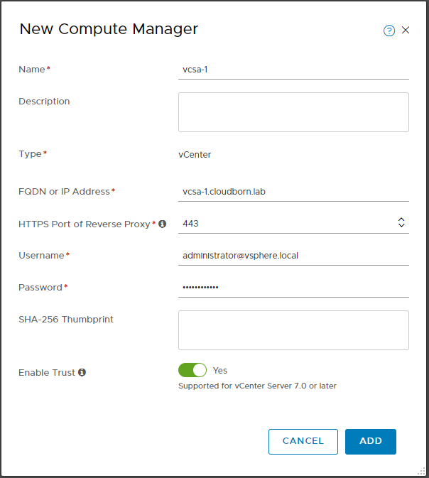
Click ADD and accept the Thumbprint.
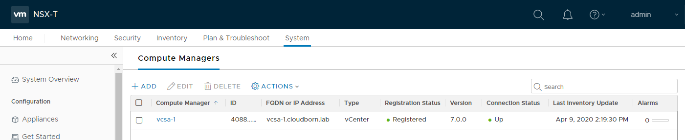
It takes a moment, but eventually, it should show Registered and Connection Status UP.
Transport Zones
Transport Zones limit, what the Host can “see”. Segments (formerly called logical switch) are assigned to one (and only one) Transport Zone. If a Host is part of a Transport Zone, VMs on that host can only be connected to a Segment that is also part of this Transport Zone.
We will create two Transportzones. TZ-Overlay which is used for all the Overlay communications (like containers in the namespace networks). Both, ESXi Hosts and EDGES will be part of this TZ.
Second, TZ-VLAN which is only used by the EDGEs. This TZ contains the Uplink VLAN, which provide connectivity between our T0 Router and the phyisical environment.
To create them, navigate to System –> Fabric –> Transport Zones –> + Add
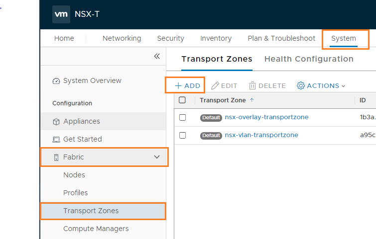
In the “New Transport Zone” Screen, configure
- Name: TZ-Overlay
- Traffic Type: Overlay
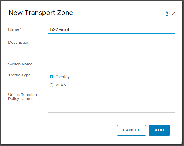
Click +ADD again. This time enter
- Name: TZ-VLAN
- Traffic Type: VLAN
Configure Transport nodes
ESXi Node Uplink Profile
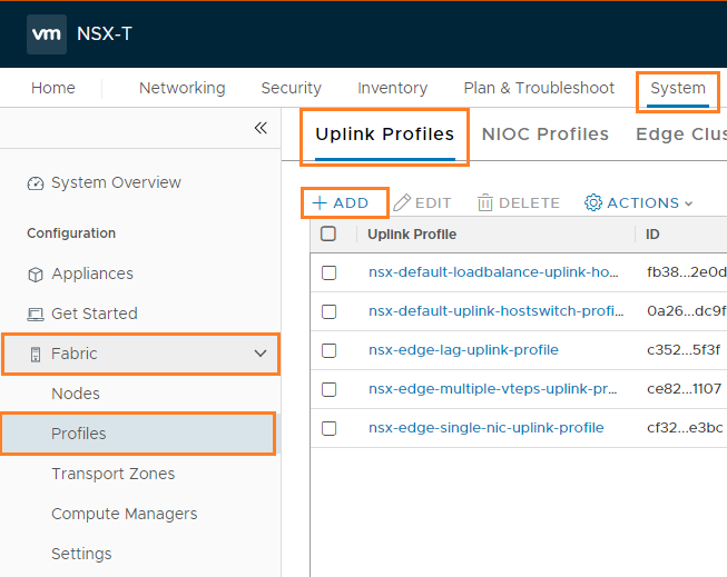
Very simplified, with Uplink Profiles, we define how the NSX environment within our ESXi Hosts (or Edges) is connected to the outside (of NSX) world.
To configure an Uplink Profile, navigate to System –> Fabric –> Profiles –> Uplink Profile –> + Add
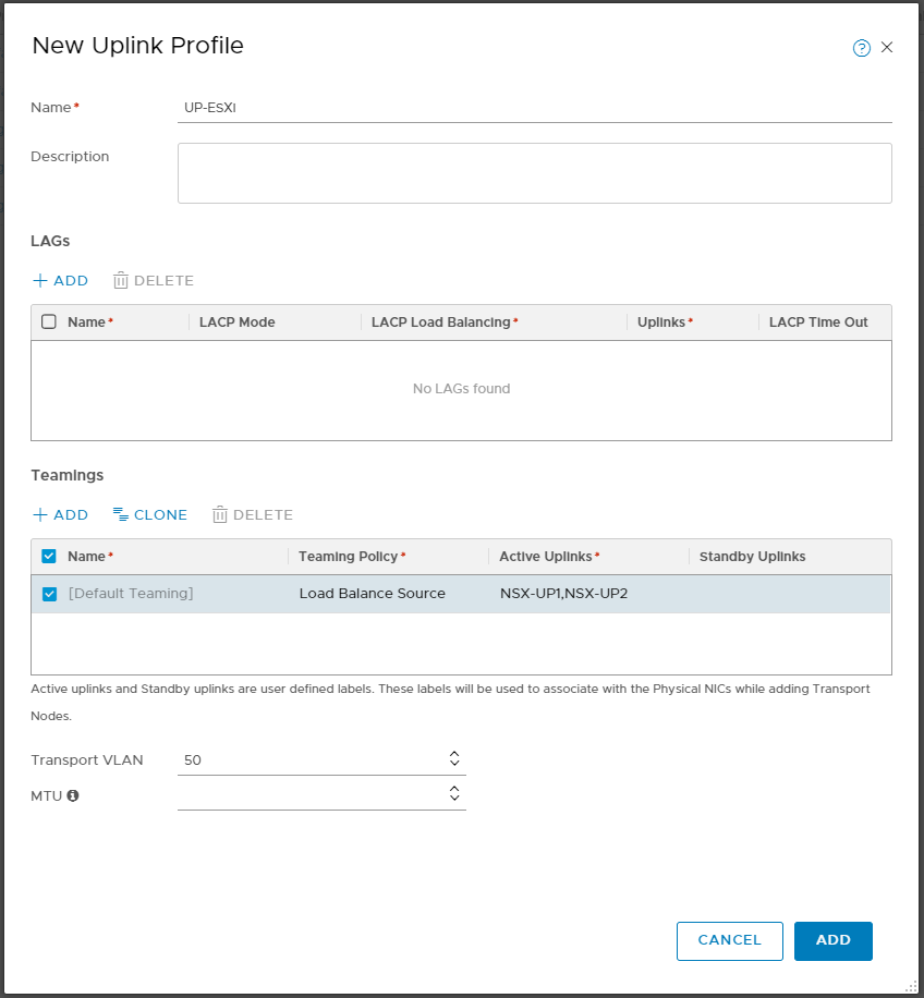
Configure the Profile as follows:
- Name: UP-ESXi
- Teamings:
- Teaming Policy: Load Balance Source
- Active Uplinks: NSX-UP1,NSX-UP2 (these are really just made-up names to identify them later, you can think of them like the traditional vDS Uplink names)
- Transport VLAN: 50
- MTU: <empty> (assuming you have nothing else configured, it defaults to 1600)
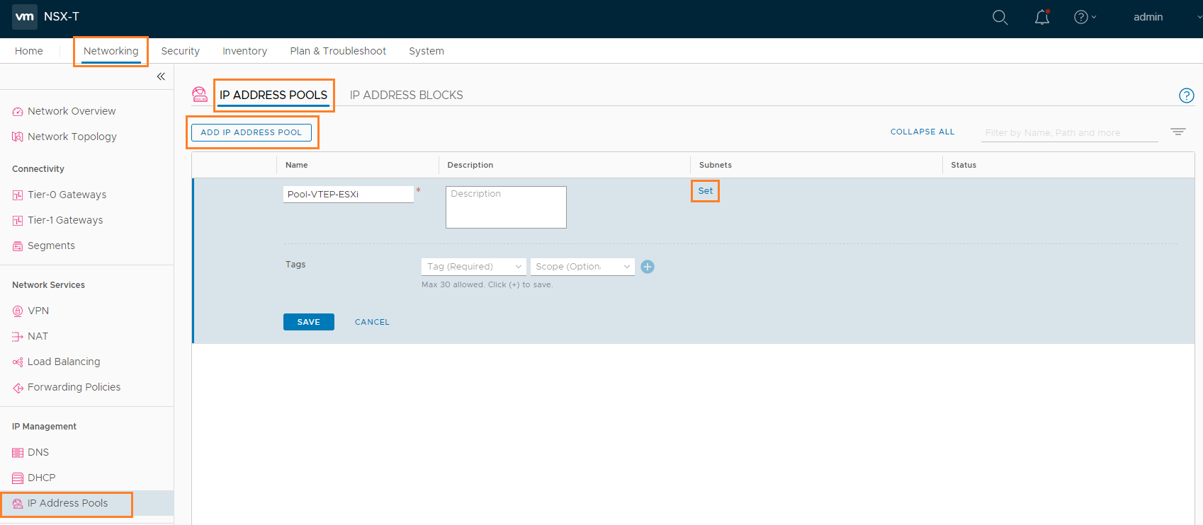
Create IP Pool for ESXi VTEPs
Next, we need to create an IP Pool, for the ESXi Tunnel Endpoints. In my case, I’m going to use Subnet 172.31.50.0/24 (VLAN 50), which we already have configured as Transport VLAN in the Uplink Profile.
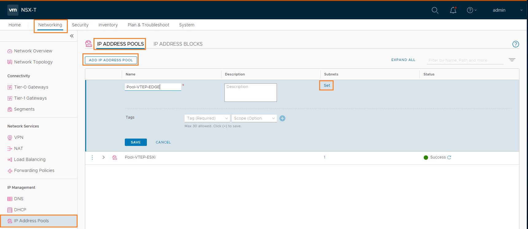
Navigate to Networking –> IP Address Pools –> IP ADDRESS POOLS –> ADD IP ADDRESS POOL
Give it a meaningful name like Pool-VTEP-ESXi and click Set in the subnet column.
In the following windows, click ADD SUBNET –> IP RANGE and enter the following values:
- IP Ranges: 172.31.50.11-172.31.50.250
- CIDR: 172.31.50.0/24
- Gateway IP: 172.31.50.1
- DNS Servers: 172.31.1.10
- DNS Suffix: cloudborn.lab
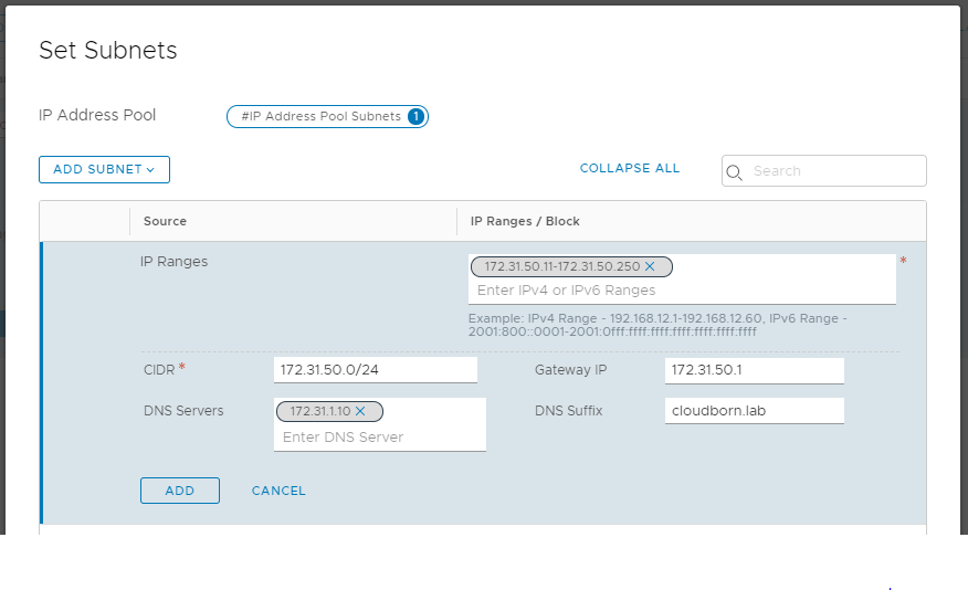
Click ADD –> APPLY –> SAVE
ESXi Transport Node Profile
Time to connect it all.
Navigate to System –> Fabric –> Profiles –> Transport Node Profile –> + Add
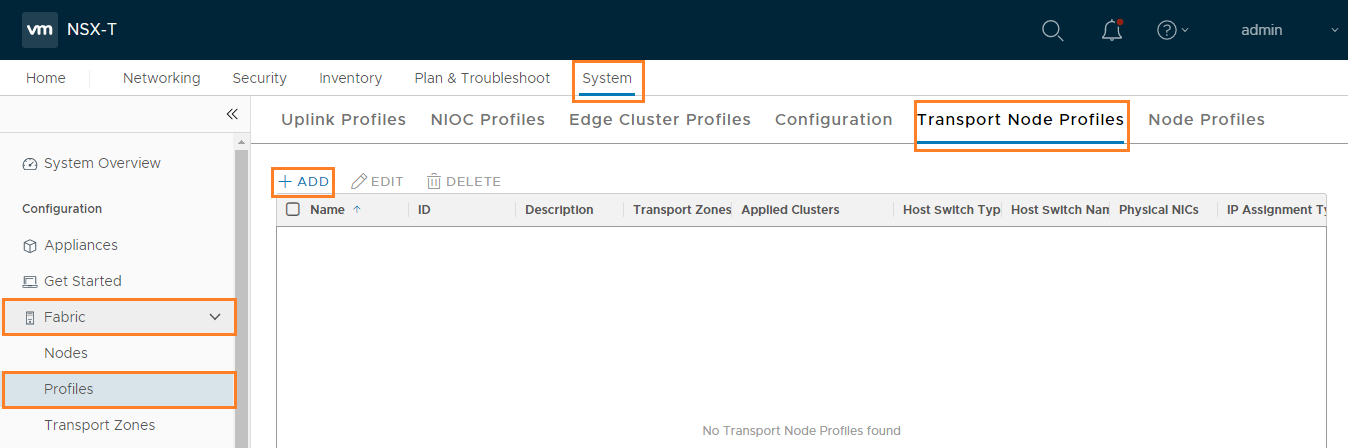
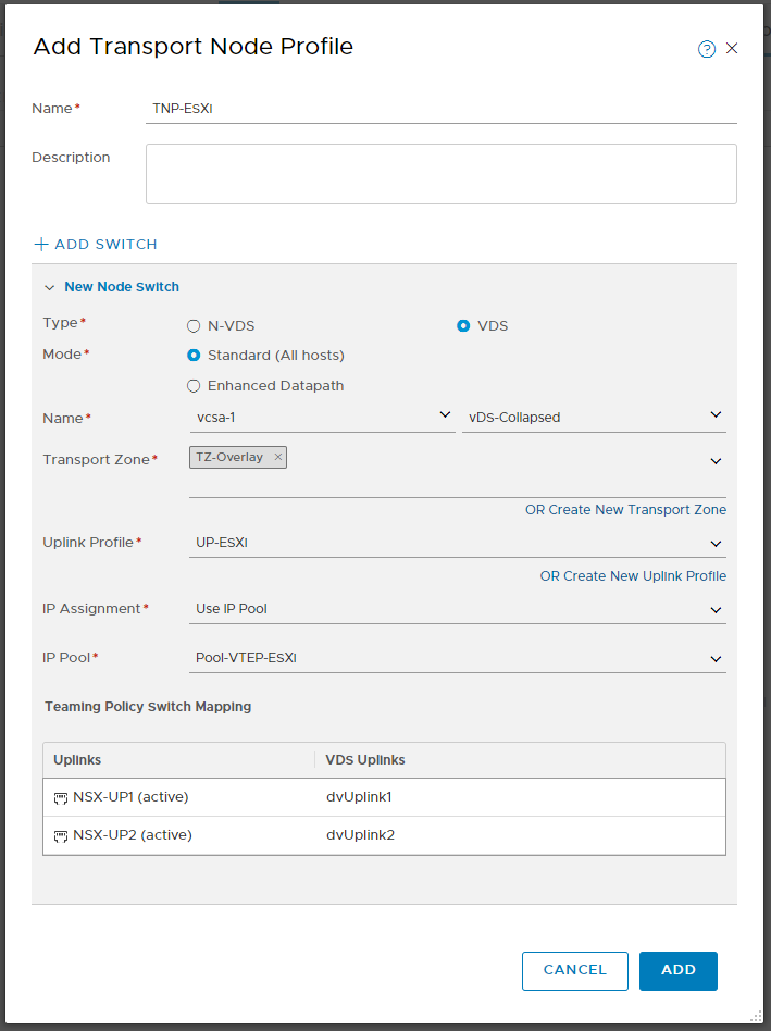
Give your Transport Node profile a name e.g. TNP-ESXi and click +ADD SWITCH (if not already happened)
- Type: VDS
- Mode: Standard (All hosts)
- Name: vcsa-1 –> vDS-Collapsed
- Transport Zone: TZ-Overlay
- Uplink-Profile: UP-ESXi
- IP Assignment: Use IP pool
- IP Pool: Pool-VTEP-ESXi
- Uplinks:
- NSX-UP1 (active): dvUplink1
- NSX-UP2 (active): dvUplink2
As you can see, this is the point, where we actually connect our transport-node internal “nsx uplinks” to our VDS Uplinks.
Prepare the ESXi Transport Nodes
Until now, we have mostly prepared Profiles. Now it’s time to actually apply them!
Navigate to System –> Fabric –> Nodes –> Host Transport Nodes
On Managed by – select vcsa-1
Select the COMP Cluster and click Configure NSX
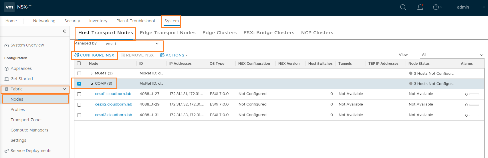
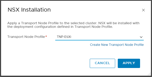
In the following Screen, select the previously created Transport Node Profile TNP-ESXi and click APPLY
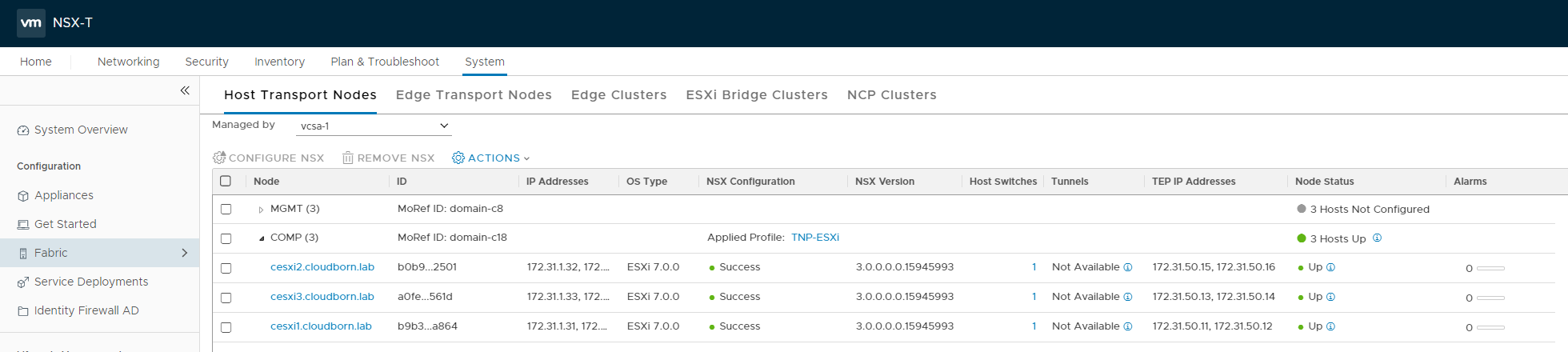
After a few minutes, you should see NSX Configuration Success and Node Status Up. Tunnels are showing Not Available, which is expected at this moment, since there are no VMs connected to any of the Segments (in fact, there are not even segments yet).
Note: There is no need to prepare the MGMT Cluster because this cluster will not connect to any Segments. If we were to nsx-prepare it too (for whatever reason), we would need to create another Uplink-Profiles and Transport Node Profile, because these Hosts have only on vmnic.
Configure Transport nodes
Our Transport Nodes are now ready to be used. Next we need to setup EDGE Nodes.
EDGE Node Uplink Profile
Similar to the Transport Nodes, we have to configure an Uplink-Profile for our EDGE Node.
Note: I will create two Uplinks the the Uplink Profile. Since my MGMT Nodes only have one vmnic, there is not much sense in doing so. I’m doing this, because I have some other plans for later down the road.
For you, it’d be perfectly fine, if you create only one Uplink.
Navigate to System –> Fabric –> Profiles –> Uplink Profile –> + Add
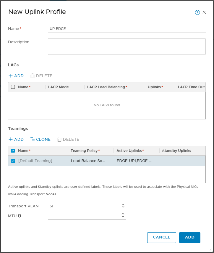
- Name: UP-EDGE
- Teamings:
- Teaming Policy: Load Balance Source
- Active Uplinks: EDGE-UP1,EDGE-UP2 (these are really just made-up names to identify them later, you can think of them like the traditional vDS Uplink names)
- Transport VLAN: 51
- MTU: <empty> (assuming you have nothing else configured, it defaults to 1600)
Create IP Pool for EDGE VTEPs
Similar to the IP Pool for ESXi VTEPs, we need to create an IP Pool for the VTEP on the EDGES. You can share the same IP Pool across TransportNode Clusters or across EDGE Nodes. But you must not share the same IP Pool between Transport Nodes and EDGE Nodes.
For the EDGEs, I’m going to use subnet 172.31.51.0/24 (VLAN 51), as we have configured as Transport VLAN in the Uplink Profile.
Navigate to Networking –> IP Address Pools –> IP ADDRESS POOLS –> ADD IP ADDRESS POOL
Give it a meaningful name like Pool-VTEP-EDGE and click Set in the subnet column.
In the following windows, click ADD SUBNET –> IP RANGE and enter the following values:
- IP Ranges: 172.31.51.11-172.31.51.250
- CIDR: 172.31.51.0/24
- Gateway IP: 172.31.51.1
- DNS Servers: 172.31.1.10
- DNS Suffix: cloudborn.lab
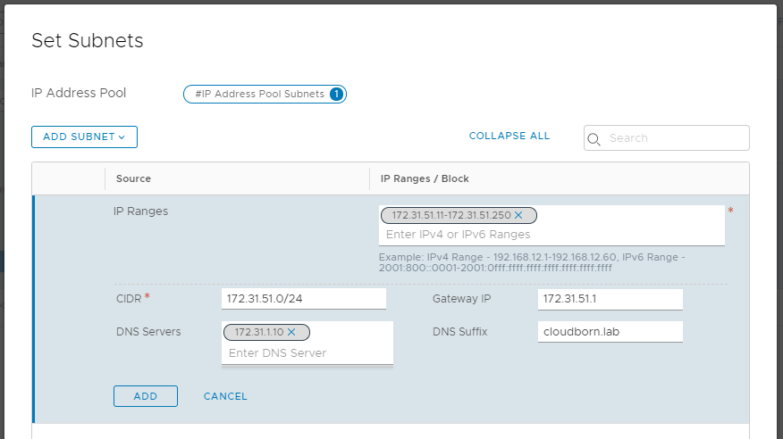
Click ADD –> APPLY –> SAVE
Deploy the NSX-T Edges
In short, the EDGES provide all the advanced / stateful router services (like NAT, VPN,…) and they also provide northbound connectivity.
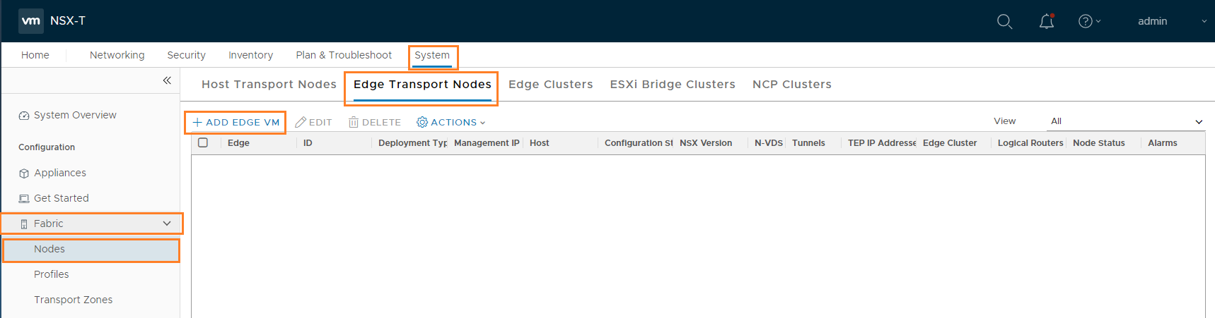
In order to deploy EDGEs, navigate to System –> Fabric –> Profiles –> Edge Transport Nodes –> + ADD EDGE VM
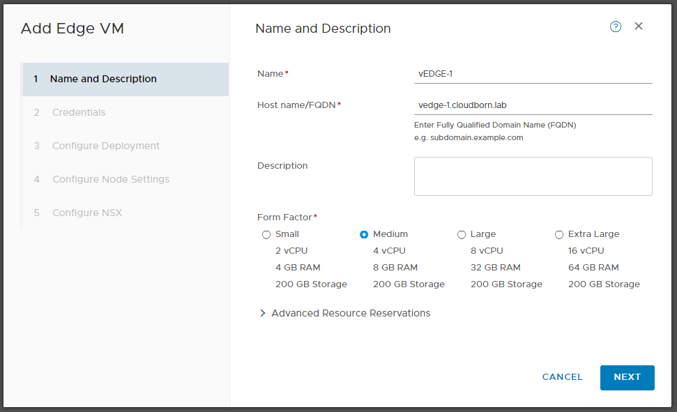
On “Name and Description“:
- Name: vEDGE-1
- Host name/FQDN: vedge-1.cloudborn.lab
- Form Factor: Medium / Large (if you plan to only use vSphere native Pods, Medium is sufficient, but if you plan to use nested K8s cluster, you need to go large, as officially demanded)
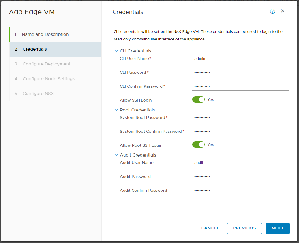
On “Credentials“, enter a valid password. I Like to enable SSH, again for potential troubleshooting later.
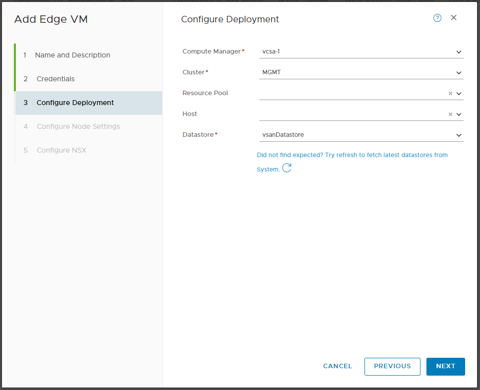
On “Configure Deployment”:
- Compute Manager: vcsa-1
- Cluster: MGMT
- Datastore: vsanDatastore
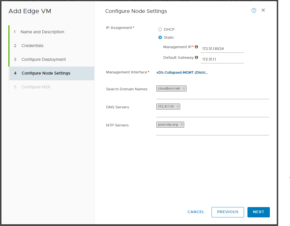
On “Configure Node Settings“:
- IP Assignment: Static
- Management IP: 172.31.1.81/24
- Default Gateway: 172.31.1.1
- Management Interface: vDS-Collapsed-MGMT
- Search Domain Names: cloudborn.lab
- DNS Servers: 172.31.1.10
- NTP Server: pool.ntp.org
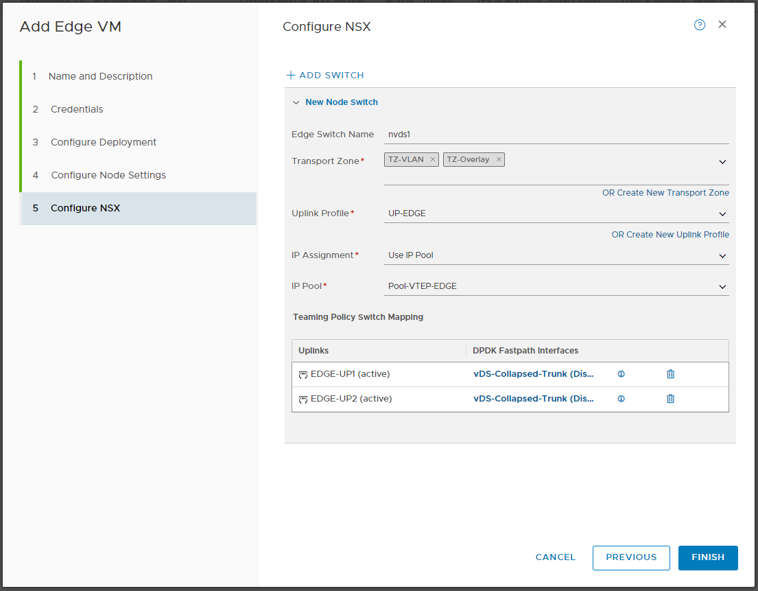
On “Configure NSX“
- Edge Switch Name: nvds1 (this is the n-vDS Switch used inside the EDGE VM)
- Transport Zone: TZ-VLAN & TZ-Overlay (the EDGE Node will provide connectivity between the Overlay Network and the Northbound Networks, therefore it needs to be part in both TZs)
- Uplink-Profile: UP-EDGE
- IP Assignment: Use IP Pool
- IP Pool: Pool-VTEP-EDGE
- Teaming Policy Switch Mappings:
- EDGE-UP1 (active): vDS-Collapsed-Trunk
- EDGE-UP2 (active): vDS-Collapsed-Trunk
Note: If you have chosen, to create only one Uplink earlier, you wont see the second Uplink here.
Click FINISH.
After a few minutes, you should see Configuration StateSuccess and Node status UP
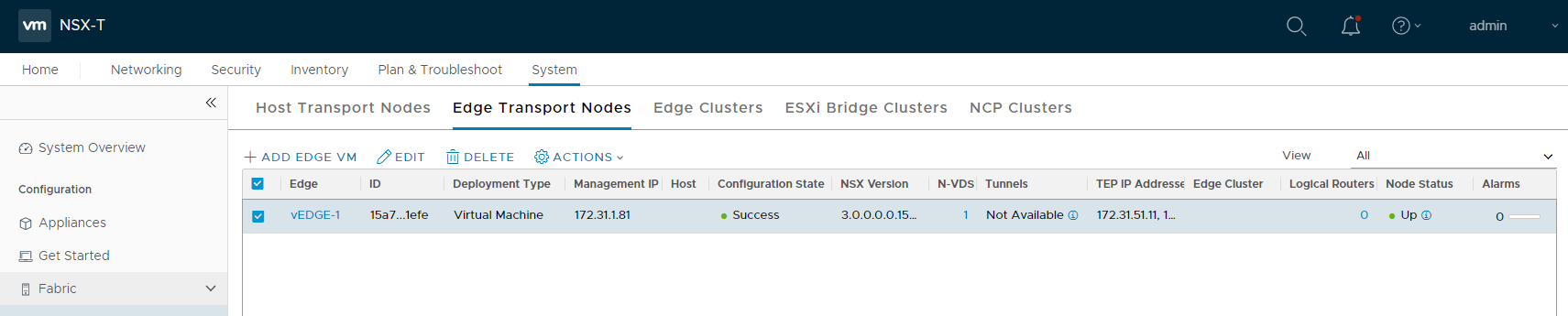
I’ll repeat the process for the second Edge (vedge-2.cloudborn.lab, 172.31.1.82). But it will also work with only one EDGE.
Note: The EDGE VM has up to four Uplinks, we are using 3 of them here. The first (eth0) is used for Management. The second (fp-eth0) and third (fp-eth1) are used for Overlay and Upstream connectivity. The way, I’ve configured the Uplink-Profile is definitely not production-ready (it doesn’t really provide a lot of fault tolerance).
Usually, you want to have two different Uplink Networks (we only have one, VLAN 60) which are running through dedicated ESXi Uplinks. Also, you want to have the EDGE Dual-Homed (BGP). For further information, check the NSX-T Reference Design Guide
Add EDGEs to EDGE Cluster
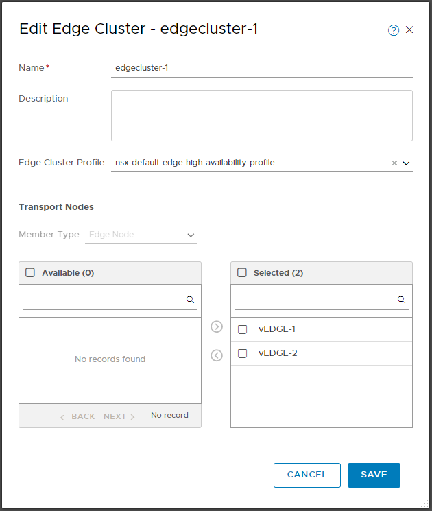
Navigate to System –> Fabric –> Nodes –> Edge Cluster –> +ADD
In the “Add Edge Cluster” window, give the cluster a name like edgecluster-1. Then Add the vEDGE-1 (and vEDGE-2 if you have it) to it (need to have Configuration Status Success) and click ADD.
Create and configure Tier-0 Gateway (aka T0 Router)
Lastly, we have to create the T0 Router, including the Uplink Segment, Router Ports and Routes. There are a bunch of different design options. Once again, since this is a Lab, its fairly simple.
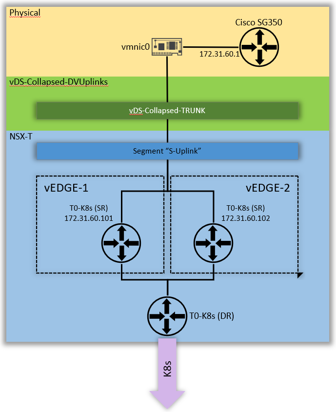
Configure Uplink Segment
You can think of this Segment as a kind of “extension” from the “physical VLAN 60” into the NSX environment.
Both, Tier-0 Gateway Uplink Interfaces and Cisco SVI are located in this Subnet (172.31.60.0/24).
To configure a Segment, navigate to Networking –> Segments –> Segments –> ADD Segment
In the Segment section, configure
- Segment Name: S-Uplink
- Transport Zone: TZ-VLAN
- VLAN: 60 (same like the Transport VLAN in the Uplink Profiles, since the EDGE VMs are connected to TRUNK Portgroups, we have to do the VLAN Tagging in NSX)
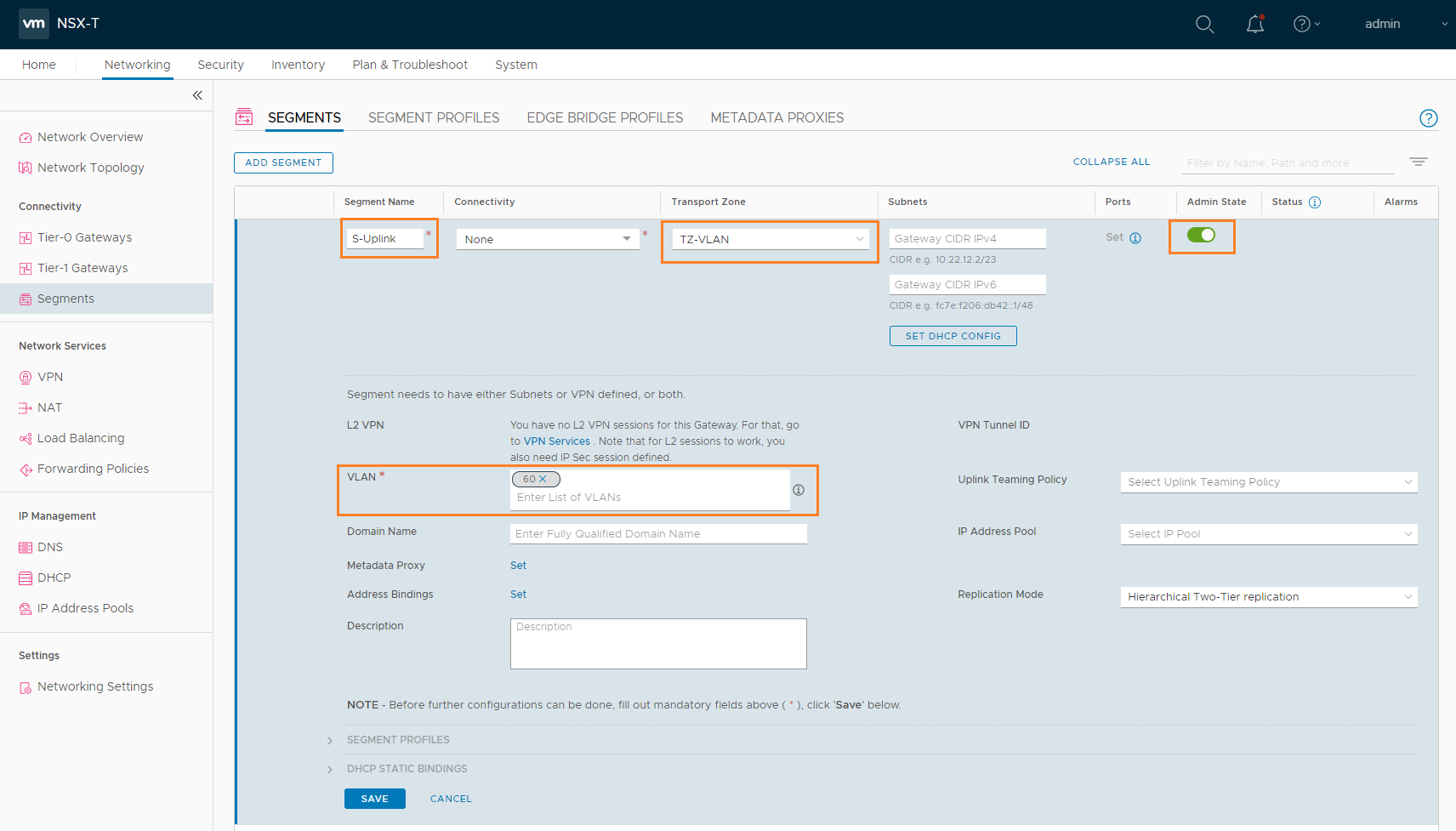
Hit SAVE
Tier-0 Gateway
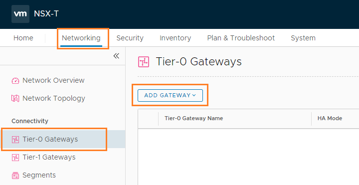
Create T0 Router by navigating to Network –> Tier-0 Gateway –> ADD GATEWAY –> Tier-0
Configure the following
- Tier-0 Gateway Name: T0-K8s
- HA Mode: Active Standby
- Fail Over: Non Preemptive
- Edge Cluster: edgecluster-1
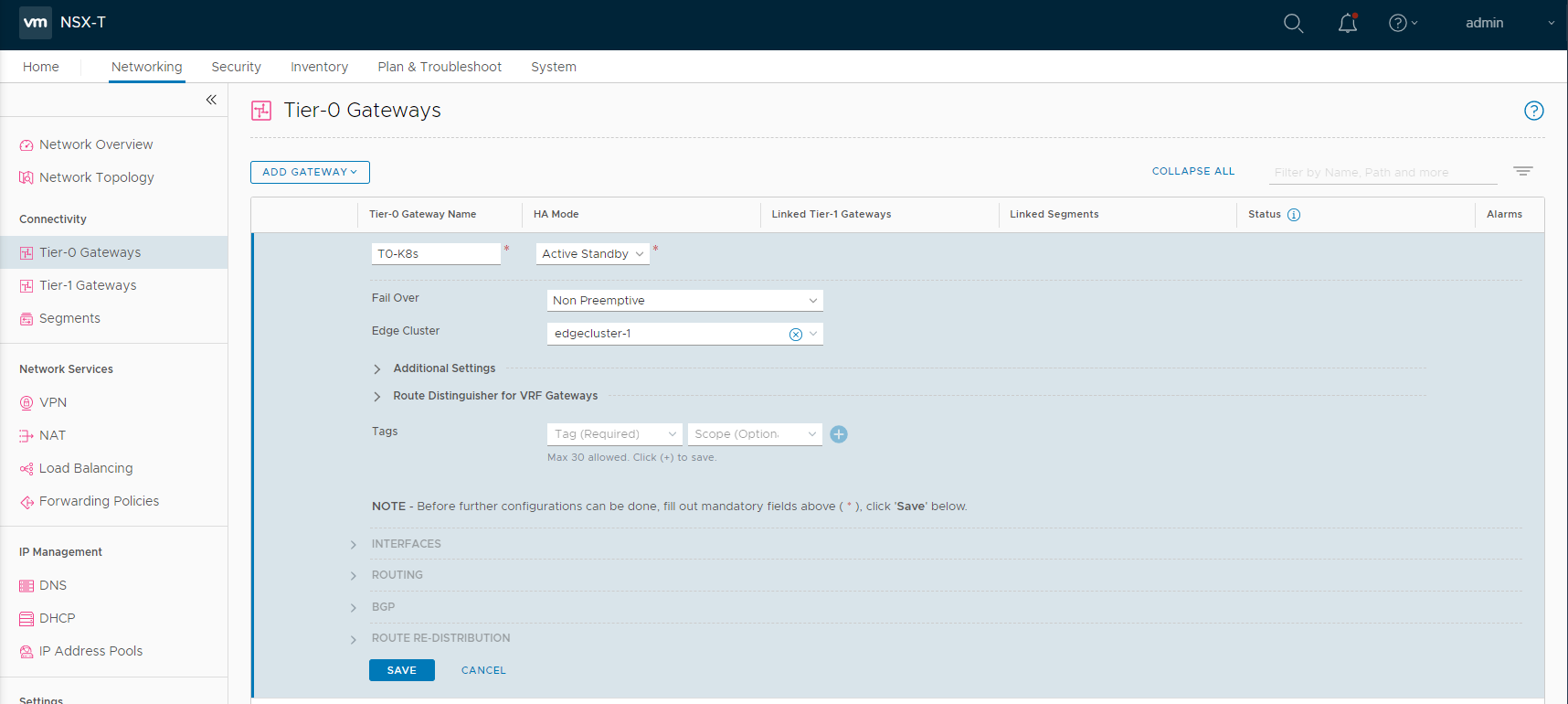
Hit SAVE, on the next screen click YES to the question if you want to configure it further.
Expand the INTERFACES Section –> click Set –> ADD INTERFACE
- Name: RP1-T0-K8s
- IP Address / Mask: 172.31.60.101/24
- Connected To (Segment): S-Uplink
- Edge Node: vEDGE-1
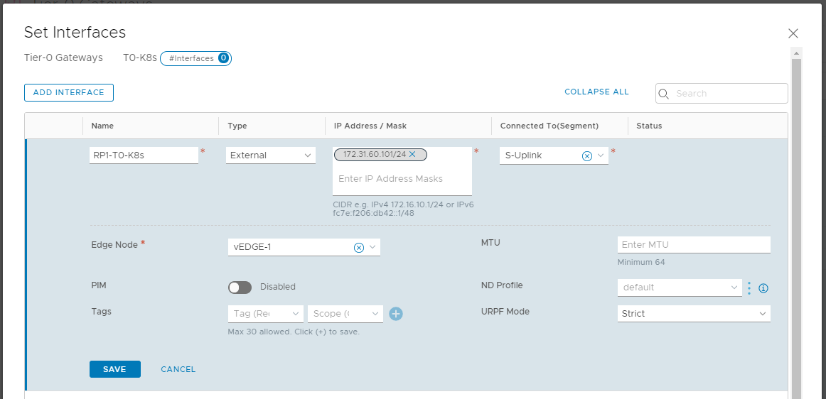
Click SAVE
If you have a second EDGE deployed and added to the edgecluster, you can configure a second interface, similar to my sketch:
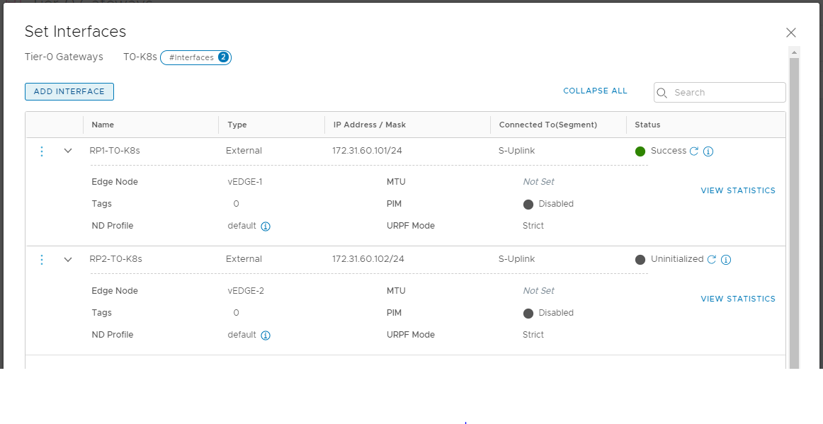
Close the Interface window and return to the Tier-0 config.
Next, expand ROUTING –> click SET next to “Static Routes” –> ADD STATIC ROUTE
- Name: T0-K8s-defaultRoute
- Network: 0.0.0.0/0
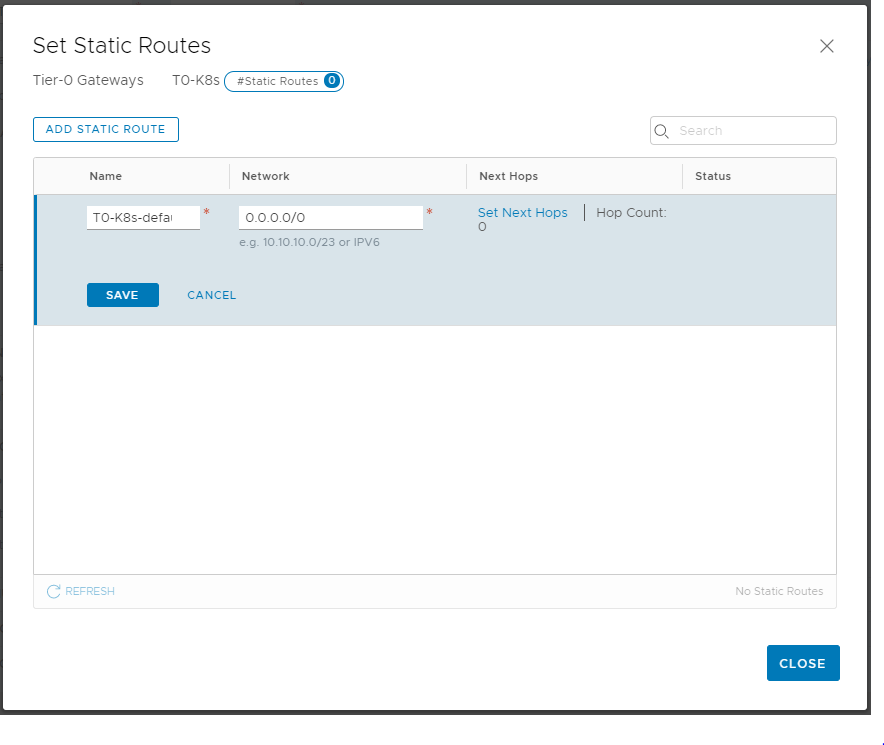
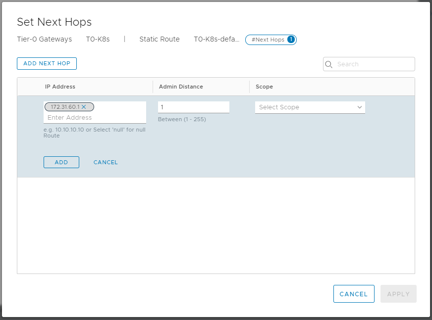
Click Set Next Hops –> ADD NEXT HOP
Add 172.31.60.1 (the Cisco Switch) as IP Address, click ADD –> APPLY
Save the route, and close the editing on your Tier-0 Gateway.
This finishes our NSX configuration. You should now be able to ping your Tier-0 Gateway. interfaces.
Next up – Basic connectivity Tests